Start from the EZCAD or SeaCAD setup files when your seller provides them.
Lens truth
1 lens = 1 profile
A 110 mm lens and a 200 mm lens should not share one guessed device profile.
Proof mark
50 mm square
A measured square reveals scale, skew, mirror, and corner problems quickly.
Last step
Rotary
Cylinder correction is not where you start. It is where you go after flat work is right.
Diagnostic matrix
Diagnose the setup symptom first
Signal
Likely diagnosis
Proof
Next move
The mark is the wrong physical size
Field size, lens profile, focus distance, or imported correction is wrong.
A 50 mm square measures 48 mm or 53 mm even though the design file is correct.
Verify the installed lens, reload the correct COR file, and recalibrate scale before tuning power.
The design is mirrored or rotated
Axis direction or galvo orientation was imported incorrectly.
Text reads backward or the preview direction does not match the burn direction.
Fix axis direction in device setup and rerun the text test on scrap.
Corners bow or stretch near the edge
Lens correction is missing, wrong, or too optimistic for the field edge.
Center marks look right, but the same square distorts near a corner.
Load the correct COR file or run galvo lens calibration for that lens.
Red framing looks right, burn lands elsewhere
The red pointer and marking beam are not aligned in software.
The red box outlines the part cleanly, but the mark is offset by a repeatable amount.
Adjust red-dot offsets after burn geometry is correct.
The mark is the wrong physical size
Likely diagnosis
Field size, lens profile, focus distance, or imported correction is wrong.
Proof
A 50 mm square measures 48 mm or 53 mm even though the design file is correct.
Next move
Verify the installed lens, reload the correct COR file, and recalibrate scale before tuning power.
The design is mirrored or rotated
Likely diagnosis
Axis direction or galvo orientation was imported incorrectly.
Proof
Text reads backward or the preview direction does not match the burn direction.
Next move
Fix axis direction in device setup and rerun the text test on scrap.
Corners bow or stretch near the edge
Likely diagnosis
Lens correction is missing, wrong, or too optimistic for the field edge.
Proof
Center marks look right, but the same square distorts near a corner.
Next move
Load the correct COR file or run galvo lens calibration for that lens.
Red framing looks right, burn lands elsewhere
Likely diagnosis
The red pointer and marking beam are not aligned in software.
Proof
The red box outlines the part cleanly, but the mark is offset by a repeatable amount.
Next move
Adjust red-dot offsets after burn geometry is correct.
Order of operations
The setup order that prevents false settings problems
Galvo setup has a trap: the machine can mark before it is accurate. A first burn does not prove the lens, geometry, red-dot position, or field size is correct.
Treat the first session like calibration, not production. The goal is a boring square that measures right, lands where the preview says it should, and looks the same near the center and the working edge.
01
Copy the factory USB before changing anything
That small drive may contain the machine file, lens correction file, screenshots, driver, and settings that make the galvo usable. Back it up before importing or overwriting files.
Bench proof
Store a dated copy of every .cor, .lbdev, .cfg, markcfg, screenshot, and vendor note.
02
Import the vendor configuration if it exists
LightBurn's galvo workflow is built around machine-specific settings. If the seller gives EZCAD or SeaCAD configuration files, import them before manually typing random values.
Bench proof
Open Device Settings and confirm field size, galvo settings, timing, and red-dot values came across.
03
Verify the lens and field size
The field size is the physical area your installed lens can cover at focus. A 110 mm lens, 150 mm lens, and 200 mm lens each need their own correction behavior.
Bench proof
Engrave a known-size square near the center and measure it with calipers.
04
Focus with a real mark, not the red dot alone
The red dot helps position work, but it is not proof that the invisible 1064 nm beam is focused. Use a low-risk material and find the smallest, loudest, cleanest mark.
Bench proof
Move Z in tiny increments and keep the height where the mark is narrow, bright, and consistent.
05
Fix axis, scale, and skew before tuning materials
If the test square is mirrored, stretched, rotated, bowed, or trapezoidal, settings cannot rescue it. Correct geometry first.
Bench proof
A 50 mm square should measure 50 mm by 50 mm and sit where the preview says it should sit.
06
Align red-dot framing only after the burn is true
A red-dot preview can be offset from the actual marking beam. LightBurn exposes red-dot settings so framing and burning land together.
Bench proof
Frame a small square, mark it, and compare the red outline to the physical mark.
07
Treat rotaries as a second setup project
Cylinder correction adds diameter, circumference, and surface-position variables. Do not debug rotary output while flat-field scale is still wrong.
Bench proof
Prove flat work first, then run a simple line wrap test on a scrap cylinder.
Autopsy
The symptom matrix
If a mark is wrong, classify the error by what it does physically. Wrong size, wrong location, distorted corners, weak focus, and rotary stretch point to different fixes.
Diagnostic matrix
LightBurn galvo setup failure matrix
Signal
Likely diagnosis
Proof
Next move
The mark is the wrong physical size
Field size, lens profile, focus distance, or imported correction is wrong.
A 50 mm square measures 48 mm or 53 mm even though the design file is correct.
Verify the installed lens, reload the correct COR file, and recalibrate scale before tuning power.
The design is mirrored or rotated
Axis direction or galvo orientation was imported incorrectly.
Text reads backward or the preview direction does not match the burn direction.
Fix axis direction in device setup and rerun the text test on scrap.
Corners bow or stretch near the edge
Lens correction is missing, wrong, or too optimistic for the field edge.
Center marks look right, but the same square distorts near a corner.
Load the correct COR file or run galvo lens calibration for that lens.
Red framing looks right, burn lands elsewhere
The red pointer and marking beam are not aligned in software.
The red box outlines the part cleanly, but the mark is offset by a repeatable amount.
Adjust red-dot offsets after burn geometry is correct.
A known setting suddenly looks weak
Focus height, lens selection, or material height changed.
The same preset worked yesterday on the same material, but the workpiece height is different.
Refocus from scratch and confirm the active LightBurn device matches the installed lens.
Rotary art compresses or spreads
Cylinder correction, diameter, or rotary calibration is wrong.
Flat work is accurate, but a wrap design does not close or is visibly squeezed.
Measure the actual diameter, use LightBurn cylinder correction, and test with a single wrap line.
The mark is the wrong physical size
Likely diagnosis
Field size, lens profile, focus distance, or imported correction is wrong.
Proof
A 50 mm square measures 48 mm or 53 mm even though the design file is correct.
Next move
Verify the installed lens, reload the correct COR file, and recalibrate scale before tuning power.
The design is mirrored or rotated
Likely diagnosis
Axis direction or galvo orientation was imported incorrectly.
Proof
Text reads backward or the preview direction does not match the burn direction.
Next move
Fix axis direction in device setup and rerun the text test on scrap.
Corners bow or stretch near the edge
Likely diagnosis
Lens correction is missing, wrong, or too optimistic for the field edge.
Proof
Center marks look right, but the same square distorts near a corner.
Next move
Load the correct COR file or run galvo lens calibration for that lens.
Red framing looks right, burn lands elsewhere
Likely diagnosis
The red pointer and marking beam are not aligned in software.
Proof
The red box outlines the part cleanly, but the mark is offset by a repeatable amount.
Next move
Adjust red-dot offsets after burn geometry is correct.
A known setting suddenly looks weak
Likely diagnosis
Focus height, lens selection, or material height changed.
Proof
The same preset worked yesterday on the same material, but the workpiece height is different.
Next move
Refocus from scratch and confirm the active LightBurn device matches the installed lens.
Rotary art compresses or spreads
Likely diagnosis
Cylinder correction, diameter, or rotary calibration is wrong.
Proof
Flat work is accurate, but a wrap design does not close or is visibly squeezed.
Next move
Measure the actual diameter, use LightBurn cylinder correction, and test with a single wrap line.
Lens discipline
The lens-swap rule most new owners miss
A larger field lens is tempting because it covers bigger work. It also changes spot size, focus distance, edge behavior, and correction needs. If you swap from a 110 mm lens to a 200 mm lens, create or verify a dedicated device profile instead of reusing a center-field preset.
Save lens-specific names in LightBurn. A boring name like 30W MOPA 150mm lens prevents the expensive mistake of firing a job with the wrong correction profile.
Buying logic
Machines that reduce setup friction
No fiber galvo is plug-and-play in the same way a consumer printer is. The best machines reduce the number of undocumented variables: common controllers, better LightBurn support, real owner communities, and clear lens files.
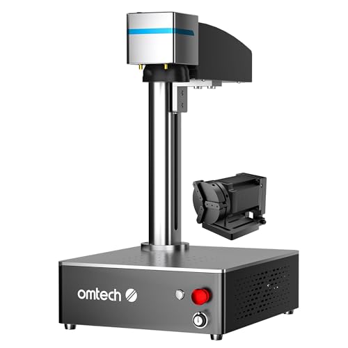
Least-friction MOPA
OMTech 30W JPT MOPA Fiber Laser Engraver
8.4
$699
Use when
You want a common 30W MOPA path with JPT hardware, LightBurn support, and enough owner knowledge to debug setup faster.
Skip when
You need the fastest possible batch throughput or a larger field included out of the box.
This guide leans on the LightBurn galvo documentation because the failure modes are mostly software, correction, and geometry problems before they become material problems.